Help Contents
Introduction
This article is a guide to connect an Allen Bradley MicroLogix 1000 PLC to Fernhill SCADA.
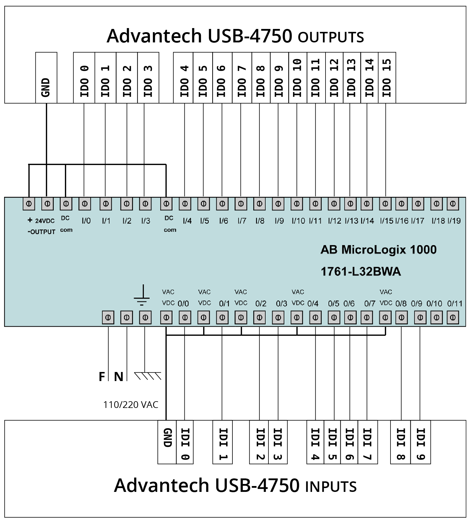
Oct 01, 2017 Lesson 2 - PLC Wiring AB Micrologix 1000 (1) In this video, i have explained how to wire the Allen Bradley Micrologix 1000. Download PDF here: https://drive. Related Manuals for Allen-Bradley MicroLogix 1000. Controller Allen-Bradley MicroLogix 1000 PLC Replacement Instructions 2 pages. Field replacement. MicroLogix 1000 Programmable Logic Controller Systems. Our Bulletin 1761 MicroLogix™ 1000 Programmable Logic Controller Systems are discontinued and no longer available for sale. Customers are encouraged to migrate to the Micro820™ PLC Systems or Micro830® PLC Systems. The MicroLogix range covers quite a few models now, from the tiny MicroLogix 1000 to the latest MicroLogix 1400 featuring online programming and ethernet communication for programming and messaging. MicroLogix Gotchas. Watch for these limitations of products in.
The Allen Bradley MicroLogix 1000 PLC has a single serial port which can be used to communicate with Fernhill SCADA. The serial port on the PLC is an 8 pin mini-DIN socket located on the left side of the PLC.
To connect a MicroLogix 1000 PLC to Fernhill SCADA these steps are required:
- Obtain a connection cable and connect the MicroLogix 1000 PLC to a PC running RSLogix 500.
- Configure the MicroLogix 1000 PLC using RSLogix 500.
- Configure Fernhill SCADA.
Connection Cables
The MicroLogix 1000 PLC can connect directly to a serial port on a Personal Computer (PC). The serial port on a PC is usually a 9 pin D-subminiature connector. These cables are suitable to connect the PLC to a computer with a 9 pin D-subminiature connector:

- 1761-CBL-AP00 - 0.5m length
- 1761-CBL-PM02 - 2m length
- 1761-CBL-PM05 - 5m length
- 1761-CBL-PM10 - 10m length
As an alternative you can create your own cable using this wiring:
| MicroLogix 1000 | PC | ||
|---|---|---|---|
| GND | 2 | 5 | GND |
| RTS | 3 | 8 | CTS |
| RXD | 4 | 3 | TXD |
| DCD | 5 | 1 | DCD |
| CTS | 6 | 7 | RTS |
| TXD | 7 | 2 | RXD |
| 4 + 6 | DTR + DSR | ||
Allen Bradley Micrologix 1000 Manual
Note: All other pins not shown in the above diagram have no connection.
Configuring the MicroLogix 1000 Serial Port using RSLogix 500
You can use RSLogix 500 to configure the MicroLogix 1000 Serial Port.
- Open a project in RSLogix 500 and in the Project window select Channel Configuration:
- Double click the Channel Configuration branch to open the DF1/485 Configuration window:
Note: Choose DF1 as the primary protocol. Fernhill SCADA does not currently support DH485.
- Click OK to save the configuration. If you have changed the configuration away from the defaults, you may receive a warning about loss of communication. Ignore the warning and, after communication is lost, change the configuration of the AB_DF1 device in RSLinx to match.
- If you lose communication after changing both the configuration of the PLC and RSLinx, you can recover using this procedure:
- Obtain a 1747-UIC (Universal Serial Bus (USB) to DH-485 Interface Converter).
- Plug the 1747-UIC into the Computer running RSLinx
- Install the 1747-UIC following the instructions in the manual 1747-IN063.
- Connect the 1747-UIC to the MicroLogix 1000 using a 1761-CBL-PM02 cable (or similar).
Note: When the MicroLogix 1000 detects a communication failure on the serial port, it will switch between DF1 and DH485 protocols. The MicroLogix 1000 continues to switch until communication is re-established. The 1747-UIC should re-establish communications with the MicroLogix 1000 using DH485.
- Change the configuration of the MicroLogix 1000 serial port using RSLogix 500.
Configure Fernhill SCADA
There are two methods to configure Fernhill SCADA to communicate with a MicroLogix 1000 PLC:

- The easiest way is to use an autodetect wizard. The wizard will try different settings to work out the correct Fernhill SCADA configuration. Use one of these wizards depending whether the PLC was configured to use Full Duplex or Half Duplex Slave:
- Manually configure Fernhill SCADA to match the configuration of Channel 0 of the MicroLogix 1000 PLC.
Manual Configuration
The default communication settings for the MicroLogix 1000 are:
| Parameter | Value |
|---|---|
| Baud Rate | 9600 |
| Protocol | DF1 Full Duplex |
| Error Check | CRC |
| Node Address | 1 |
The Fernhill SCADA configuration that corresponds to these defaults is:
| Allen Bradley Serial Port | ||
|---|---|---|
| Mode | Baud=9600 Parity=N Data=8 Stop=1 | |
| Protocol | DF1 Full Duplex | |
| ErrorCheck | CRC | |
| Allen Bradley PLC | ||
| Destination Node | 1 | |
Further Information
For information about Allen Bradley serial channel configuration.
For information about Allen Bradley PLC Tag configuration.
Allen Bradley Micrologix 1000 Programming Manual
For background information on serial communications.

For information about the Allen Bradley Driver.
For the meaning of terms used in Fernhill SCADA.
Fernhill SCADA Version 3.47. Copyright © 2012-2019 Fernhill Software Ltd: All rights reserved.